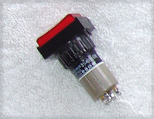


High quality, long life Swiss panel switches which are typically used in professional broadcast panels.
These switches have been carefully removed from some KLOTZ panel operators equipment
EAO
Made in Switzerland
Confirmation of this is stamped into the rear of the switch
Series 97 switch (now a discontinued line from EAO)
Type: 97-320
Exceptional electrical operating characteristics ... ≥ 500,000 operations (that's a LOT of button pushing!)
PCB mount using the 4x pins plus there is a "locating plastic pin"
Normally open - momentary make
Only for low voltage, low current use (typically switching digital circuits)
Maximum 42V @ 50mA current
Gold plated switch contacts
Supplied with the clip on lens and White diffuser (blank)
Installed is a standard 2mm RED lead and this is not a permanent fit so you can change the LED colour to whatever suits your situation or leave it out completely.
All switches are supplied with the front clear clip on lens and the internal White diffuser square. To label these, use a thin piece of something like vellum, onto which the desired text is placed - you could use Letraset or something similar for this.
The front window or lens clips into place on top of the switch, to lift off the lens just use something like a flat bladed jeweller's screwdriver (must be very small) and gently prise at the junction of the window and the switch body - it will just pop off. To re-instal, place in position on top of the switch (making sure the tiny recess is facing downwards) and apply light pressure, you should hear it "click" - job done!
I am not supplying the labelling vellum, currently when the LED is powered up, the front of the switch will glow RED with no text showing.
Some dimensions ...
Switch assembly: 14.65mm length x 12.3mm x 12.3mm (front moving section) OR 12.65mm length x 10mm x 10mm
(rear static section)
This means the switch is 27.3mm total length when not pressed and upon fully pressed, the length is 24.5mm i.e the top section has 3mm of travel.
The small square of vellum required for labelling is 10mm x 10mm
Originally these were mounting on PCB sub-boards and by using spacers between the PCB board and the Operators panel, the correct spacing was achieved when the switch is activated.
TESTING:
Being "pulls" and relatively easy (very little heat required) to remove from the PCB, I have undertaken the laborious task of testing every single switch function.
Open = infinity Ohms
Closed (depressed) = unable to measure accurately due to test equipment limitations but the reading was well under 0 Ohms, we are talking milliOhms here.
Electrical switch action was immediate, with the quick and decisive change of state and looking at the scope, very low contact bounce was seen.
I have not bothered testing the LED's, it is quite likely that the new owner will fit their own (Blue, Green, Yellow etc) 2 wire LED's but in any case I have no reason to believe anything would be amiss with the LED's.
Easy to remove these LED's, just two holes in the rear of the switch and no tricky moulding.
To maintain the current condition of these switches, I have individually packed each switch into a sealed clear plastic packet.